
Maze Game - Matthew G 2022
Welcome to GDD310 - Intro To Unreal!
Let's learn Unreal Engine!
We focus on creating a strong foundational understanding of the Unreal Engine, starting with an exploration of the editor and its many tools. We then work our way through the core concepts of game development, leading into the creation of custom Blueprints using Unreal's Blueprint Visual Scripting system. Through engaging demonstrations and an iterative game design process, students who complete this course will have mastered the fundamentals of Unreal and generated portfolio-worthy content that will bolster their future job searches.
How It Works
This course is run asynchronously: I provide recorded lectures and material on this website for you to follow as you complete work which is assigned each week. To submit work, on Blackboard, you will need to provide links to zipped Unreal projects that I can download. You can host the zip files on mywebspace, One Drive, Google Drive, or anywhere else you would like, as long as I have the ability to download them from a URL that you can submit.Section 1
Tuesday / Thursday 1:30PM - 2:45PM
Location: SITE 105
Location: SITE 105
GDD310 Showcase

Exercise 1 - Getting Started
Installing Unreal Engine and Starting Your First Project
In this exercise we will begin learning how to utilize the Unreal Engine to develop games.
We start with an exploration of the editor interface and various tool available inside the development environment.
Maze
Once we have explored the editor layout, we will begin our first project: The Maze. Building a maze will allow us to create a simple starter game which we can build upon as we learn new skills.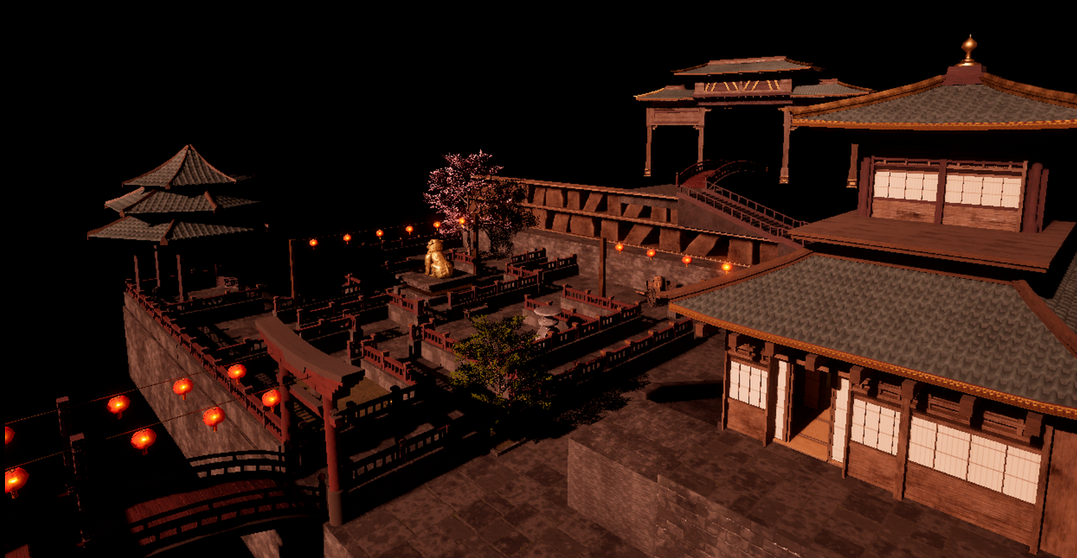
Maze - Jai H 2024
Starting Your First Project
- Download and install the Epic Games Launcher
- Install Unreal Engine 5
Create Your Project
-
From the Epic Launcher select Launch Unreal Engine
- Select the Games category to show templates for creating new games. These can provide you with useful assets and functionality to get you started.
- Select the Blank project template. We will look at the others in the future.
- Leave the project defaults as they are. We will explore these options another time.
-
Choose a location on your ,machine to create the new project. Choose a path on your hard drive with no
spaces or special characters. ex:
c:/Unreal/Projects. - Choose a name for your project. Avoid spaces and special characters.
Exercise 1 - Unreal Editor
Getting to Know the Unreal Editor Interface
In this exercise, we will begin learning the Unreal Editor and it's various tools, editors, and windows.
Understanding where each window and editor is will be neccesarry to utilize all of the features of Unreal.
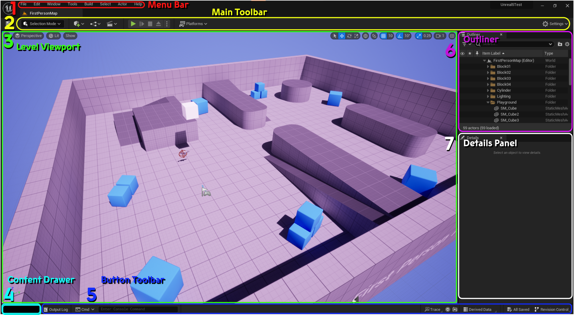 Documentation The Unreal Editor
- 1. Menu Bar
- 2. Main Toolbar
- 3. Level Viewport
- 4. Content Drawer
- 5. Button Toolbar
- 6. Outliner
- 7. Details Panel
Exercise 1 - Create A Level
A level can contain level geometry, actors, lighting and environmental effects, and more.
Create a Level
Documentation LevelsWe will be creating a new, empty, level. From there, we will add a few actors to help get a sense of how to utilize the editor.
- Your game assets live in project's Content folder. Open the Content Browser to see your games assets.
- A game generates many assets, so organization is important. Create a Levels folder inside the Content folder.
- To create a new level, you can go to
File > New Level. We are using an Empty Level.
More info about the other level types. - Save your level to the Levels folder you created earlier. Go to
File > Save Level
Adding Shapes
Create simple level geometry with simple 3D shapes.- To add a common actor to the level, use the Create list. Create a Cube by going to
Shapes > Cube. - To view and modify properties of an actor, look at the Details panel. Set the position of your cube to
(0, 0, 0)to center the cube in the level. - You can
Hold Right-Click + WASDto navigate around the viewport. Move the view so that the cube is in the center. - The default view mode for the viewport is Lit. This will render the viewport as it will look in game, with light sources illuminating the level. Without any light sources yet in our level, our Cube should be impossible to see, however Unreal prevents this from happening. Switch the view mode to Unlit to see the level fully illuminated, even without light sources. Then switch back to Lit to get an accurate look at your level without lights.
-
Add a Directional light to your level to see it in Play mode.
Create > Lights > Directional Light. A Directional light can be though of like the Sun. It emits light from a direction, instead of from a single point like a light bulb. We will cover lighting in more depth later.
Exercise 1 - Adding Content From Fab
To add new models, textures, sounds, fonts, and other assets, to your project, you need to import them into your project.
One easy way to find assets for your game is to utilize the Fab Store, built into the Unreal Editor. We will look at how to find free
materials for our project, and in a later lesson, we will learn how to build our own materials.
Adding Materials
- To change the look of the assets in your levels, you will need to apply Materials to them. We will dive deeper into materials later, but for now we want to find an easy way to add new materials to our project.
- In the Content Browser, click the button.
- You will need to log in / make an account if you haven't already done so.
- On the menu, filter the assets for Materials.
- You can filter the assets by various attributes, including price.
- Use the Search bar to filter by name.
-
The Search Results will now display assets that match your query. Find an asset that you would like to use.
Some assets will have Quality options for you to choose from. Lower quality materials will require less storage space, higher
quality materials will have higher resolution and higher space requirements.
Note In the Quality options for models, you may see "Nanite". This is a very large file size option, but also has benefits we will discuss later. - Select to begin downloading the asset to your project's Content folder.
- I repeat this process for a second material now.
- Select the Actors that the new material will be applied to. Use
Ctrl + Left-Clickto select multiple Actors. -
Once a material has been downloaded, select a Cube, and find the Materials property in the Details panel.
Some models will have more than one material slot on them. The Cube only has one, so Element 0 refers to the single material slot for the Cube model.
Select the drop-down menu next to Element 0 to select a new material for the slot, and select the material you downloaded from the Fab store. You should see the Cube now rendered with the new material. - I repeat this process for the floor Cube now.
Exercise 1 - Create a Blueprint
A Blueprint is a group of components, data, and behaviors. Blueprints utilize a visual scripting system that allow you to program your actors without writing any code. We will make a simple Blueprint for now, and explore them in more depth later.
In this lesson we will be creating a "Wall" blueprint to help create walls in our level. The wall will have a hole in the middle to see through.- Before creating your first Blueprint, add a Blueprints folder.
-
To create a new Blueprint, add a new Blueprint class to your Blueprints folder.
You can use the button, or
Right-Clickinside the Content Drawer. - In the Pick Parent Class window, choose Actor. We will dive deeper into what this means in a later lesson.
- Double-Click on your new Blueprint class to open the Blueprint Editor. You can dock this window inside the main editor window to create a tab.
- There are currently no components on our Blueprint. Add a Cube from the Components panel by hitting the button and searching for "Cube".
-
You can change the
position, rotation, and scaleof a component by changing these values on the Details panel, with the component selected in the Components panel. You can also use the shortcut handles to manipulate these values by pressing "W", "E", or "R" keys in the Viewport, or clicking the appropriate buttons at the top of the viewport. -
To make a duplicate of the lower wall section, select the "Cube" component and press
CTRL + Dor useRight-Click > Duplicateon the component. - Use the Translate (Move) handles by pressing "W" to raise the new Cube on the Z-Axis.
- Continue to duplicate and move Cube components as needed to create a wall with a hole in the middle.
Exercise 1 - Import Unreal Character Controller
To allow your players to walk around your level, you can utilize one of the character controllers provided by Unreal. These can be
selected at the time of creating a project, or imported later. In our example, we chose a Blank Project when we started, so
we'll need to import this.
The First Person Template provides a set of Blueprints that enable a well designed First Person Character Controller, along with
a ball launcher that can be picked up and fired.
- To find the Unreal First Person content, open the Content Drawer and click the button. Then select the button.
- Select the First Person option and press .
This will add several folders and Blueprints to your Content folder. You can find the First Person Character Blueprint inContent > First Person > Blueprints > BP_FirstPersonCharacter. We will explore this in a future lesson. -
Once the content is added to your project, we need to add a Player Start actor to the level. Find it in
Quick Add > Basic > Player Start. This is where the player will begin when the level starts.
Position the Player Start capsule in a place where it is unobstructed. -
Currently, the game does not know that we want to use the BP_First_Person Blueprint as our player character.
This information can be set in a Game Mode Blueprint, a Blueprint which contains data about the game. You can find this
Blueprint in
Content > FirstPerson > Blueprints > BP_FirstPersonGameMode.
To tell our level to utilize this new Game Mode, find the World Settings panel and inGame Mode > Game Mode Overrideselect the BP_FirstPersonGameMode blueprint. - After placing a few Cubes in the level, hit ▶️ Play to try it out!
Assignment 1 - Create a Maze
The objective for your first Assignment Set is to create a maze. The player should start at one position inside the maze and attempt to navigate their way to the end.
You should use primitive shapes like Cubes, Spheres, Cylinders, and Cones.
You must create at least 1 Blueprint and use it in your maze at least 3 times.
Consider using a Blueprint for anything that gets used more than once, which can occur frequently inside a maze.
Remember to include all of the required content detailed on the grading page.
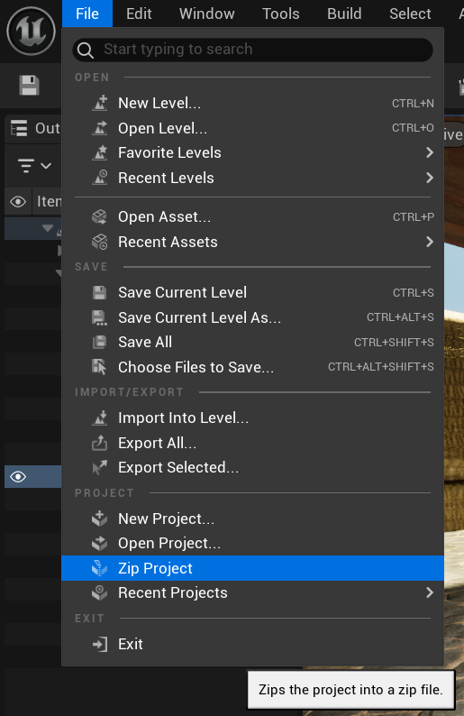
To create a zip file of your project, in the Unreal editor use File > Zip Project. This will generate a
compressed file that you can then upload to MyWebspace, Google Drive, or One Drive.
Example 1: Tower Escape
- This is a Climbable Maze, where the exit is at the top of one of the towers.
- The Tower is a Blueprint, which has a few commonly placed platforms and windows.
- To make the level more interesting, additional ramps and platforms are placed around the 3 Towers in the level.
Example 2: Garden Maze - Jai H 2024
- Jai used various assets to construct a beautiful maze in the center of this village.
- The Blueprint contains the low concrete wall and red wooden fence to make for easy building blocks to construct the maze inside the level.
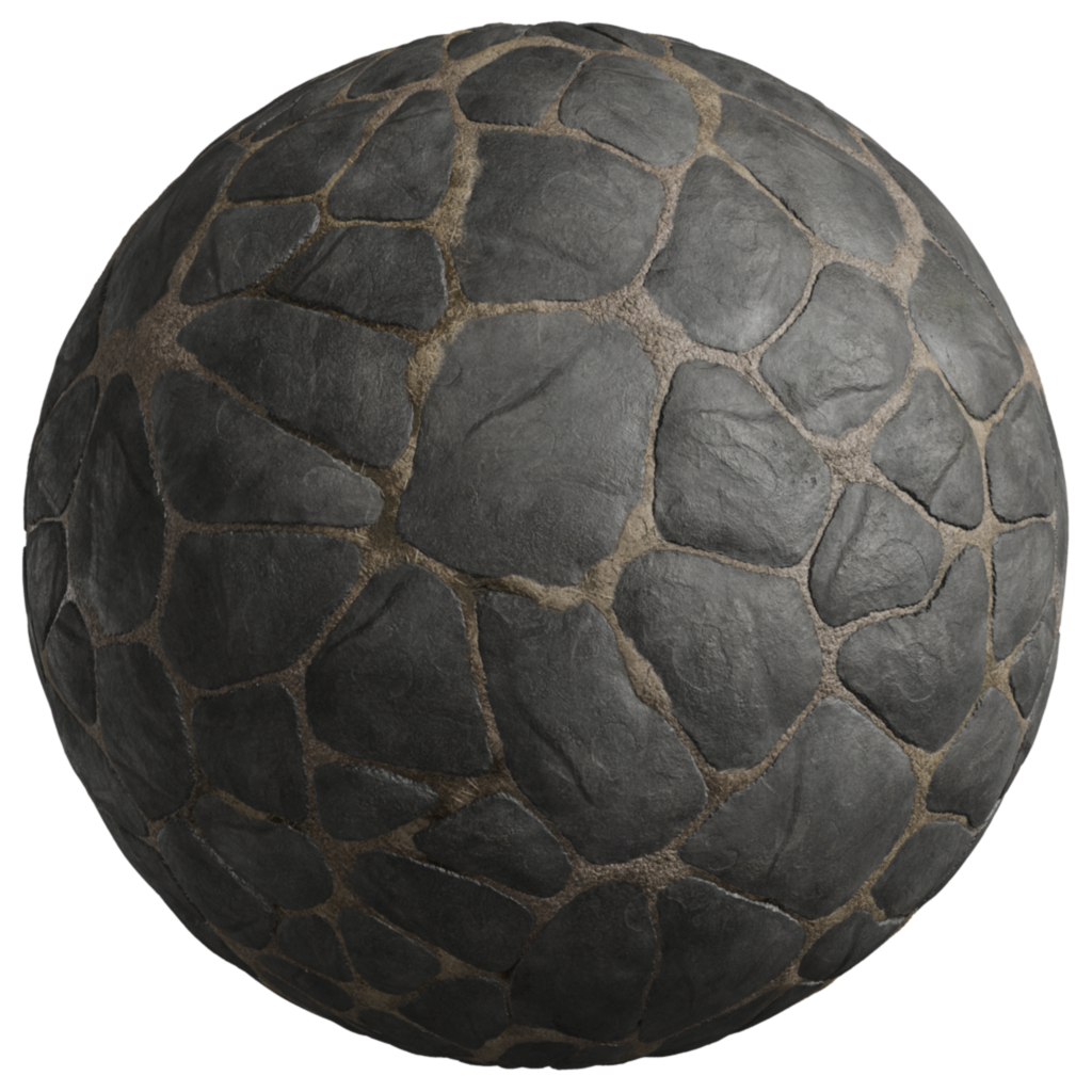
Exercise 2 - Materials
Learn how to use the Material Editor to create a PBR Material for Unreal.
When creating assets for a game, artists often require the use of combinations of textures to generate realistic or stylized effects.
To apply these textures to a mesh, or 3D model, in game, a Material is used to combine these textures and deliver the look the developer wants.
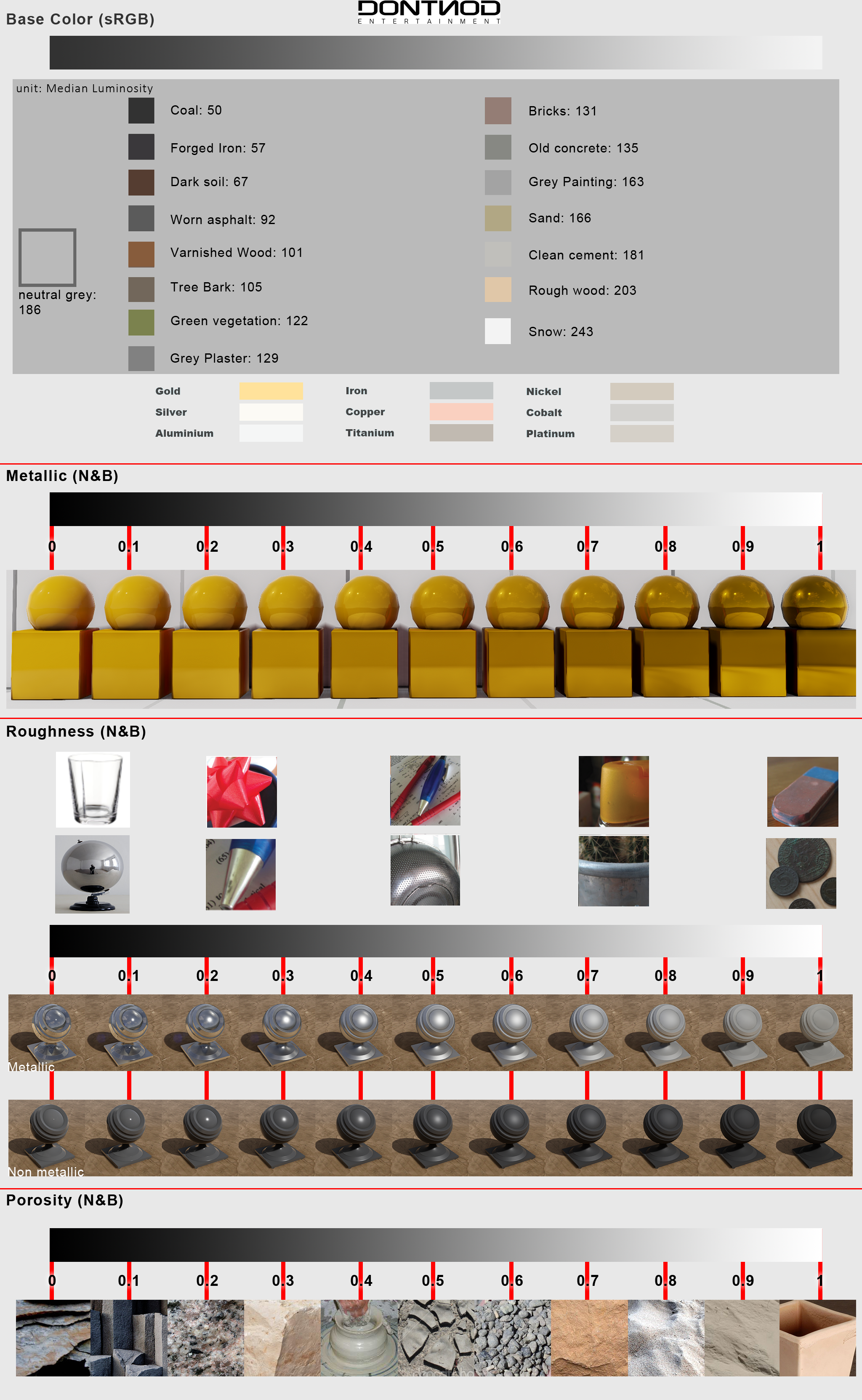
Documentation Physically Based Materials
Exercise 2 - Creating A Material
Materials created in the Material Graph work by chaining together Nodes and plugging them into Inputs on the Result Node at the end.
- Start by creating a folder for Textures and another for Materials.
-
Add your textures to your Textures folder. If they are in a .zip folder, you will need to unzip them.
I'm using 7 Zip to unzip mine, you may need to use a different method, both Windows and Mac have built in methods for unzipping compressed files. - Once the unzipped textures are added to your project, the editor will detect these and ask if you would like to import them into your project. Once imported, the textures will appear in your Content folder.
-
In your Materials folder, create a new Material.
> Material
Double-Click on the material, or press Enter, to open the Material Editor. - The Top Left viewport in the Material Editor shows a preview of your material applied to an example mesh. As changes are made to the material, the preview will update.
- The tall node, with the name of your material on top, is the Result Node. Other nodes are plugged into the result node to determine input for each property. The Base Color node can use a Color Tint modifier to change the color output.
-
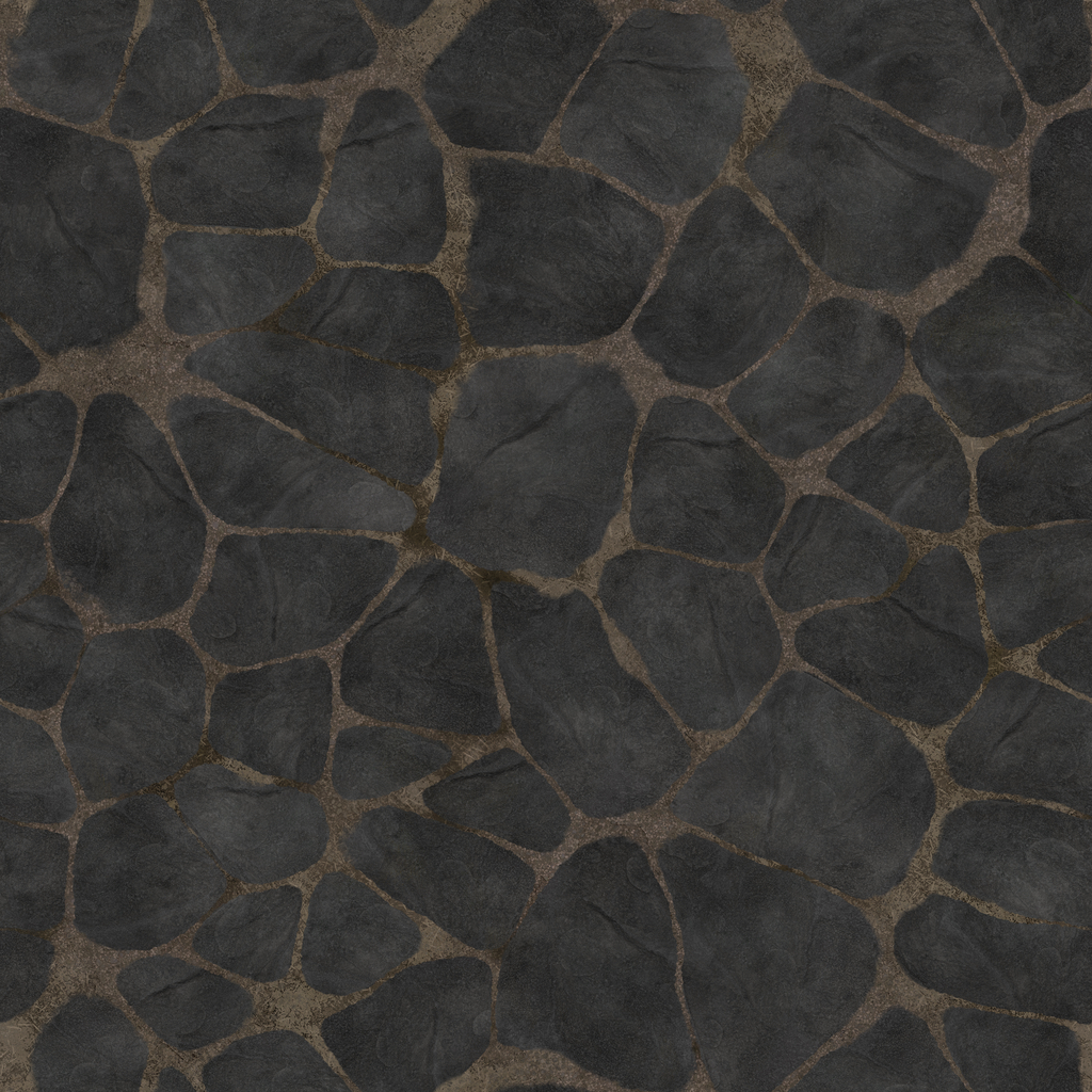
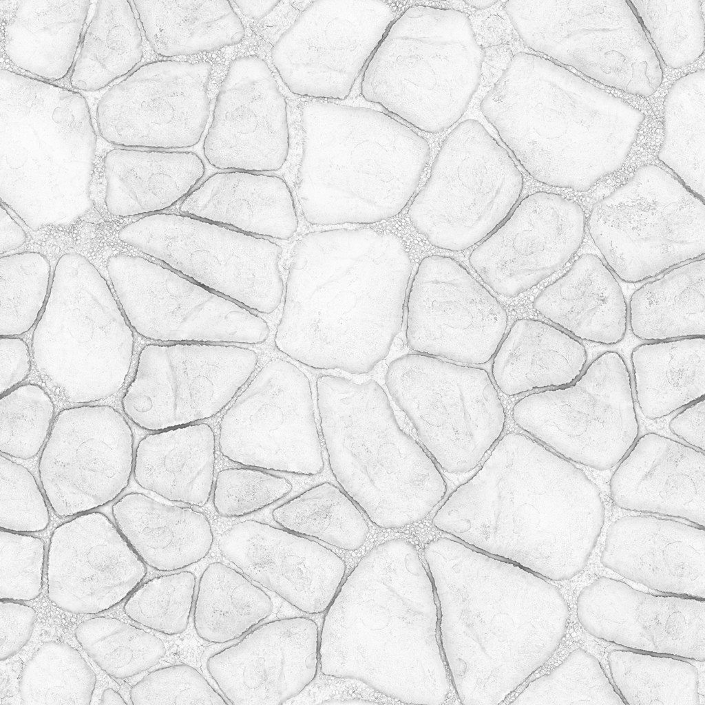
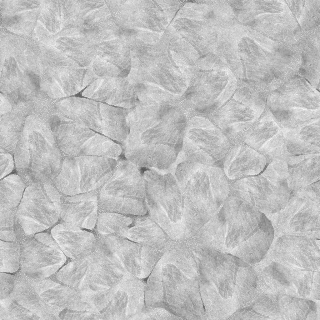
To apply our textures as inputs to the Result Node, drag them into the Material Editor Graph from the Textures folder. In this example, I will be
applying Color, Normal, Ambient Occlusion, and Roughness textures. We will explore others in later lessons.
By dragging a texture onto the Material Graph, the graph adds a Texture Sample node with the selected texture applied to the node's Texture property.
Select multiple textures by holdingCtrlwhile clicking on them. -
On the Texture Sample node with the Color Texture selected, click and drag the pin next to "RGB". This is output of this node, in this case the full color texture.
Drag this RGB output into the Base Color Input node on the Result Node. The preview will update with the color texture applied. Continue to plug the Texture Sample nodes outputs into the appropriate Result Node inputs:
- Color Texture > Base color
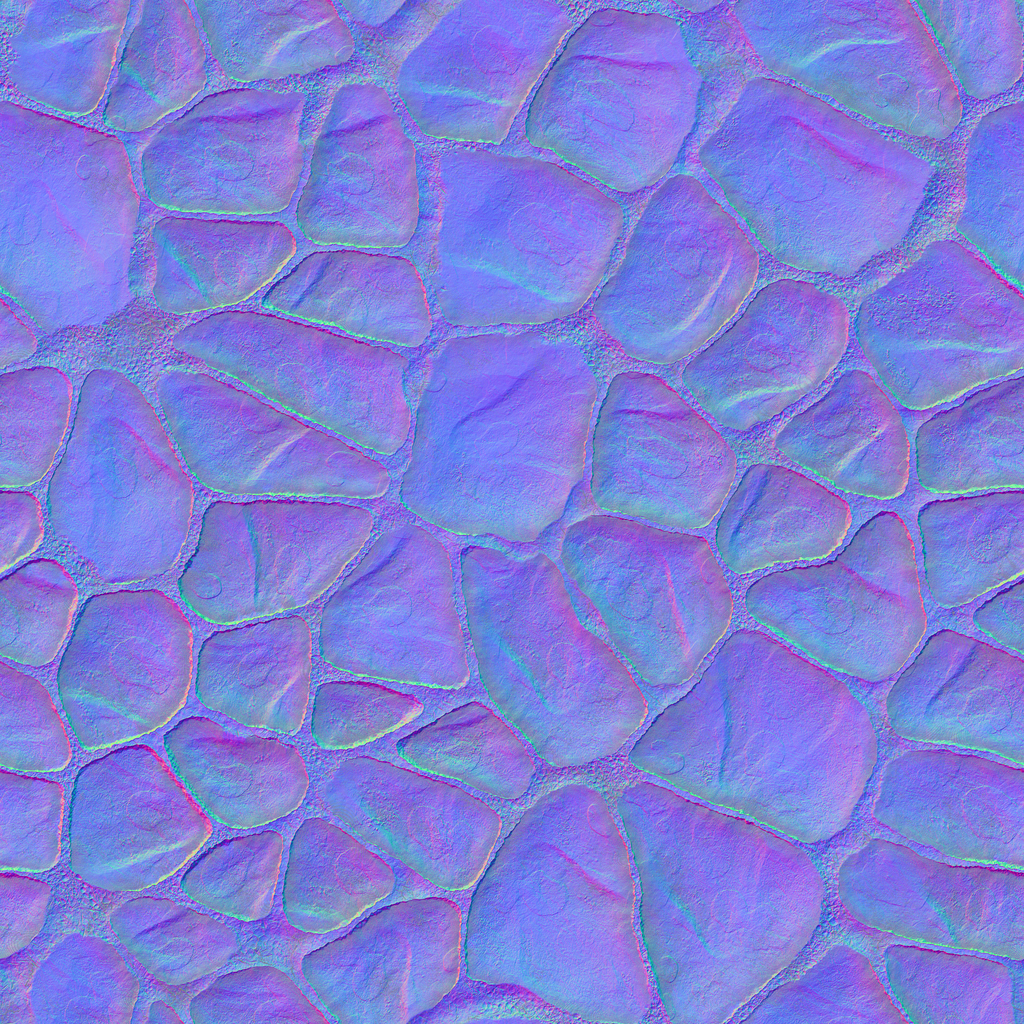
- Normal Texture > Normal
- Ambient Occlusion Texture > Ambient Occlusion
- Roughness Texture > Roughness - Save the material, and apply it to the Material property of a mesh in your level or Blueprint.
Exercise 2 - Material Instance
Material Instances allow you to create variations of a base material. This allows for unique settings while sharing a
common inheritance between instances. Consider a paint material for the hood of a car. They might have common reflection and
clear-coat styles, but have a different color.
To make Material Instances work, exposed parameters in the base material are editable in the instanced material.
- Here is an example of a tile material, using just a color texture. Break the link between the Texture Sample node and the Result Node input.
-
Drag a pin off of the RGB output on the Texture Sample Node and release the mouse button to see the node search prompt. Find the Multiply node.
Connect the output of the Multiply node to the Color input on the result node.
The color is now the result of the Texture Sample being multiplied by1.0, meaning it looks no different. However, if the texture is multiplied by0, the result changes dramatically. -
Multiplying by a single float value results in shades of grey, but to apply full RGB tints we'll need to use a
Constant3Vectorinstead. This provides a float input for the Red,Green, and Blue values.
drag the pin off of the lower Multiply input and search forConstant3Vector. Now, select a color. -
By changing the value of this
Constant3Vector, the color of the tile changes. To make this property editable on instances of this material,Right-Clickon the node, and selectConvert To Parameter. Save the material. -
Now we can make an Instance of this material.
Right-Clickon the Material and findCreate Material Instance. This will create your Material Instance asset.Double-Clickthe asset to open the Material Instance Editor.
At the top of the Details panel, find the Parameter you created. Toggle the parameter to enable an override, and then make a change to the values.
Now this Material Instance can be applied to a mesh!
Exercise 2 - Scalable Texture
To create a material which enables instances to be stretched on the X and Z axis, we will modify the Tile material from the previous example.
- This material appear to be stretched along the Z axis. Let's modify the material to allow it to be corrected.
-
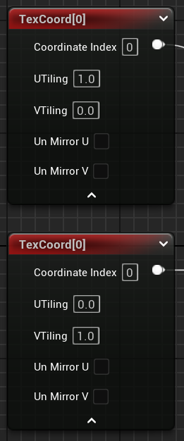
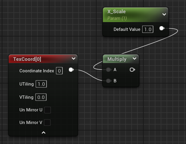
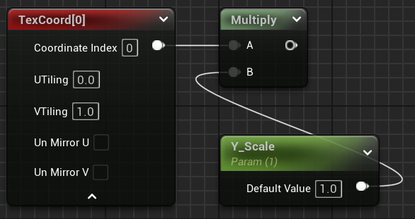
Start by adding two TexCoord nodes to your material graph. Expand the node to expose the U Tiling and V Tiling values.
On the top TexCoord node, set the V Tiling value to 0, and on the lower TexCoord node set the U Tiling value to 0. This will enable each axis to be scaled independently.
-
To give the material instances a way to control these values, use a Multiply node. Connect the output of each TexCoord node to
it's own Multiply node. Then, for the other input of the Multiply node,
Right-Clickthe input pin and select Promote To Variable.
The TexCoord node with the U Tiling value of 1 controls the scaling on the X Axis, so name the Parameter in that sequence "X Scale".
Name the other "Y Scale".
-
To combine the two TexCoord paths, use an Add node. This node provides two inputs that are combined into one output.
Use the output of each Multiply node as input for the Add node.
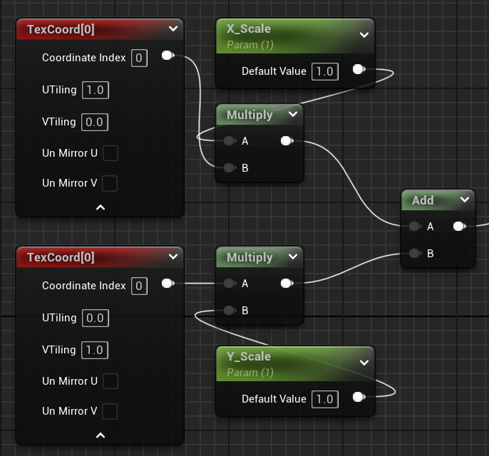
-
The output of the Add node can now be plugged into the UVs input of the Texture Sample node.
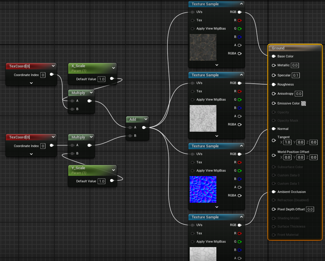
Now, when editing instances of this material, the X and Y scales can be changed to make the material appear correctly. -
Additional Example: To apply scaling to a material with multiple textures, plug the
Add output into each Texture Sample UVs input.
Exercise 2 - Lighting
The Lumen Engine provides unlimited realtime diffuse light bounces, allowing scenes to glow with realistic color.
Image from Unreal Engine DocumentationLighting Documentation for UE5
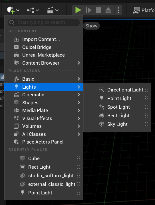
- Lights can be added to a level with the Quick Add Menu.
- Lights can also be added to Blueprints as Components.
There are several types of lights that can be added to your game.
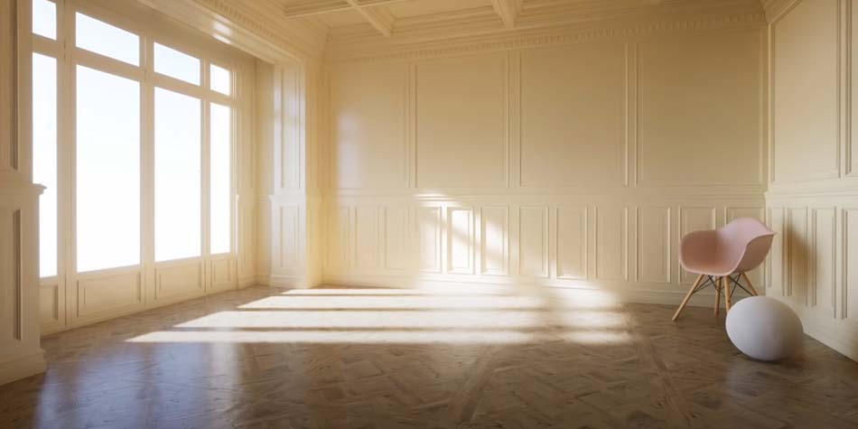
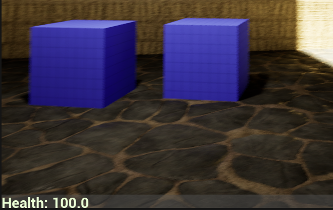
- Here is an example of a Directional Light shining through a doorway. You can see the result of Lumin's realtime Global Illumination as the light hitting the Blue cube is reflected onto the surfaces around it.
- A Rect Light provides a rectangular light surface from which light is emitted. The Source Width and Source Height define the size of the light source, which can be seen in the reflection of the mirror below.
- A Spot Light emits light in a cone shape from a point. The length and angle of the cone can be used to control light.
- Point Light sources emit light in all directions from a point.

The properties for most lights are similar and the tooltip (shown when the mouse hovers over the name of a property) provide enough context
to understand them.
Indirect Lighting Intensity can be used to control how much this light contributes to Global Illumination, the strength of the reflections of this light source.
Assignment 2 - Sounds
Sound effects and music play a crucial role in creating a game environment that feels complete and immersive.
Audio cues can be effective means of communicating with the player, informing the player of what's happening in the game even if they don't see it.
Ambient sounds can immerse a player in the game world, making the level feel like they're in a real place. Music can be used to evoke feelings in the player.
Playing background music & ambient sounds
- First, you'll need to find the music file you wish to play. Take a look at the Resources page for help finding assets.
- To create background music or ambient sounds, we want to play a sound which doesn't change in volume as the player moves around. Start by creating a new Blueprint and choosing Actor as the Parent Class. Name the new Blueprint "Music Player".
- Drag the new Blueprint into the level to create an Actor.
-
Open the Blueprint Editor (
Double-Click on the Blueprint) and open the Event Graph. This is where the logic and behavior of actors is created. - There are three Event nodes on the graph by default, Begin Play, Actor Begin Overlap, and Tick. We want this actor to begin playing the music when the game starts, so click and drag the ▶️ arrow from the Begin Play event, then release to show the Executable Actions panel. This will display actions that can be performed when this actor starts.
-
Use the search field to find the Play Sound 2D action. This will add a new function to your graph, with a line connecting it from Begin Play to
Play Sound 2D. This line defines the order of execution for your script. The Play Sound 2D function requires a Sound value to be selected. Choose
your music file.
Compile your Blueprint. - Now, as long as you have added your Blueprint to the level, you should hear your music play when you run the game.
Playing sound from a location
- Before you begin, make sure you have a sound effect imported into your project. Check the Resources page if you need help locating or creating one.
-
If you want your sound effect to loop, open the sound effect details by
Double-Clickingon the sound file. FindLoopingand enable it. - To enable the sound to change volume as the player's distance changes, Sound Attenuation, create a Sound Attenuation asset by opening the Add menu in your content browser and searching for "Sound Attenuation". Name the asset, then open it.
- In the Sound Attenuation settings, change the Attenuation Function to "Natural Sound" to cause the sounds falloff to behave more realistically.
Assignment 2 - Add Materials & Light
The objective for the second Assignment is to update your Maze project with materials and lights.
You can use materials from the Fab store, but you must create at least 1 material yourself, adding Texture Sample Nodes to the material graph.
You should also add at least 3 different types of lights, Point, Spotlight, Directional Light, or Rect Light. Use the lights to create a feeling about the
level, see if you can direct the players eye, and movement, using materials and lights.
Use sound effects and music to create an immersive experience for your players.
👀 Watch: Half Life 2's Invisible Tutorial - See how environmental design, lights, and materials, can be used to teach and guide a player.
Example 1: Cabin In The Woods - Jai H 2024
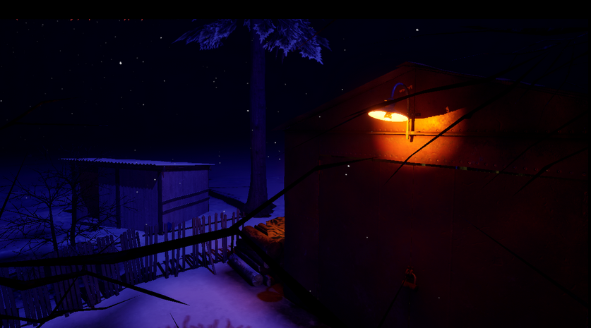
- Jai made great use of lighting to create a mysterious atmosphere and drive the player toward their objective.
- There are many effective materials throughout the level that anchor the player to the game world.
Exercise 3 - Blueprint Editor
Blueprint Classes are instructions for creating actors in your game. The Blueprint defines things like:
- Components: Independent features added to your Blueprint: a mesh, light, or a camera.
- Variables: Properties that belong to the actor: health, their name, or a collection of items they own.
- Behavior: Programming that controls the actor: making a character walk when a player presses a key, a switch that turns on a set of lights, or an NPC that walks between two points in a level.
When a Blueprint is added to a level, it becomes an Actor that can have it's own properties and behaviors. For example, an enemy Blueprint might define
how much health an enemy starts with. Then, when the enemies are added to the level, they each maintain their own health value.
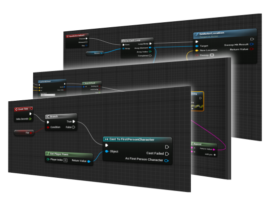
Unreal Engine provides a method of writing scripts for your games using a visual scripting system.
Events call functions and follow a path outlined on graph, weaving a series of nodes into the functionality behind your game.
Visual scripting allows you to easily navigate script execution flow through each node, where you can reference variables and utilize common programming features like collections and loops.
We will learn how to get started with the visual scripting system by creating interesting game elements for our maze, and then you will build your own unique blueprint from the ground up.
Event Graph Shortcuts:
Creating a Blueprint - Viewport
In this example, we will create a button that a player can stand on. Next, we will implement the scripting needed to give the button functionality.- Create a new Blueprint and name it "Button".
- Open the Blueprint Editor and ensure the Viewport window is opened. This window shows what the Blueprint will look like inside the level, if it has any visual components.
- In the Components panel, click the button and use the search field to find a Cylinder. This will add a component to the blueprint which has a cylinder static mesh, a 3D model.
-
With the new Cylinder component selected in the Component list, the Details panel will display the Cylinder's properties. Change the scale on the Z-Axis
to
0.1. - I've added a second cylinder, made it slightly smaller, and raised it up a bit. With this cylinder selected, look at the list of available materials and select one.
- To allow this button to detect a player standing on it, add a Collision component. This acts like a trigger that the Blueprint can detect other actors entering. This just adds the component, the scripting in the next lesson will make it work.
- The required components are now in place, add the button to your level. Next, we'll wire up the scripting to get the button to work.
Creating a Blueprint - Event Graph
In this example, we will continue building our Button Blueprint. We will use Unreal's Visual Scripting system to program our button to print a debug message and play a sound. We eventually want ensure that only the player can trigger the button.- Return to the Button Blueprint, and open the Event Graph. This is where the scripting for a your Blueprint is written.
-
The Event Graph for a new Blueprint comes with three events. Find the
Event ActorBeginOverlapnode. This event will be called when an actor, like a Player, Ball, or Enemy, passes through it.
When an event is called, the chain of functions connected via the Exec ➧ line will execute in the order they fall along the line.
Nodes may have other pins on them as well, these might be Inputs, data that can be passed into the node, or Outputs, data that can come out of a node. Some nodes also have multiple Exec ➧ lines that can divert the path of execution based on a condition evaluated in the node.
Drag a line off of theEvent ActorBeginOverlapnode and release it to see the search window. Find and select thePrint Stringaction. -
The Exec ➧ line should now flow from the Event ActorBeginOverlap node into the
Print Stringnode. This means that after detecting an overlap with another actor, the first thing that this Blueprint will do is print out a message to the console. If we want another action to occur, we have to add it to this chain of actions.
For now, look at theIn Stringfield attached to thePrint Stringnode. This pin allows a string to be passed into the node, dictating what string it prints. Alternatively, we can type a new string into the input field.
NoteThe ⮟ drop-down arrow offers more options for printing messages to the console. - The trigger should now work, compile your Blueprint and run the game. You should see the message print out to the top-left corner of the screen when the player stands on the button.
-
Next, add a
Play Sound At Locationaction after thePrint Stringto play a sound effect when the button is triggered. Use the location of the button actor as the location to play the sound.
This works for our Player, but what happens if we drop a cube onto it also?
To enable physics behavior on the cube, I first duplicate (Ctrl+D) a cube. Then, in the details panel, on the Transform category set the Mobility to Moveable. Next, in the Physics category, check Simulate Physics. In the Collision category, enable Generate Overlap Events. -
To ensure only our Player triggers this button, we can use a
Castnode. This will analyze the Actor which triggered the event to see if it is of a certain class. In our case, we want to make sure that the Actor that triggered it is aBP_FirstPersonCharacter, the character controller from the First Person Template.
To perform this check, drag a line off theOther Actor 🔵pin on theEvent ActorBeginOverlapnode. This will be a reference to the Actor that entered the button's trigger. We want to use this as the input for our cast, so now search for "Cast To BP_FirstPersonCharacter". This will add the new action with the input field plugged in, ready to check if that actor is a player. -
Next we must control the flow of this event's logic.
Because we only want to play the sound when the Player steps on the button, we need to perform this check before anything else happens. To make theCastaction occur before thePrint String, drag a new line from theEvent ActorBeginOverlapnode's Exec ➧ pin and attach it to theCast To BP_FirstPersonCharacteraction.
Now, because we only want to continue the event if the triggering actor was the Player, plug the top Exec ➧ line into thePrint Stringaction. This line will be followed if the result of the Cast was successful. If it was not, meaning the actor that triggered the event was not a Player, the Cast Failed ➧ line will proceed, allowing for a different behavior to occur.
Note TheAs BP BP_FirstPersonCharacter 🔵pin at the bottom of the Cast node gives us a reference to the Actor that hit the trigger, as the BP_FirstPersonCharacter, meaning we could reference the players properties and call functions on the Player if we wanted, for example, to give the player health or ammo.
Blueprint Variables
- Starting with a version of the button which only triggers when a player steps on it, we can use a variable to control what a button prints out when triggered.
-
In the Variables panel, press the button to add a new Variable to this Blueprint.
This variable will contain a String that should be printed to the console when a player steps on the button, so name the Variable "MyMessage".
To make the type of variable a String, open the Variable Type Dropdown next to the variable name and select String.
NoteSome common types of variables:
●String: Text like letters and words. Names, messages, dialog, etc.
●Boolean:TrueorFalsevalue.IsAlive,GameStarted,IsFriend.
●Integer: Whole numbers.
●Float: Decimal numbers.
●Vector: 3D Vector. Velocity, Aim Direction, Angular Velocity. -
Once the name and type of the variable is set, it can be dragged off the variable list and into the Input pin for the Print String function. The color of the pins
lets you know the type of variable that an input or output uses, so the ● on the InString input of the Print String node requires
a String as input.
What happens if you make a Float type variable and plug it into the Print String node? - To set the value of "MyMessage", you must first compile the Blueprint and then look to the Details panel. There will be a field besides each variable that allows it's value to be set. Set a value, compile, and test the game.
-
To allow variables to be set for individual instances of Blueprints, a different message for each button, make the variable Public.
This will cause the variable to show up in the Details panel of an Actor when it's selected in the level Outliner.
Compile the Blueprint, then duplicate (Ctrl + D) the button. Set the "MyMessage" value of each button in the Details panel.
Setting Variables in Event Graph
- Add the Begin Play event back to the Event Graph. This event is called when this Blueprint starts in a game.
-
To set the value of a variable in a script, drag the variable onto the graph. A Get or Set selector will appear.
Get: Get a reference to the variable. Useful if you want to read the value only.
Set: Set the value of a variable, overwriting it's previous value.
Flow Control : Branch
To control the flow of a script, various flow control nodes can be used. These can cause blocks of code to loop or evaluate conditions to control which path an event follows.Documentation Flow Control in Unreal Engine
-
Create a new ● Boolean variable to store the locked-state of the button.
A Boolean value is either
TrueorFalse, so the button can check this value and execute a different set of actions based on the state. - Compile the Blueprint to enable setting the value in the Details panel.
- Move the nodes after the Cast function over to make room for evaluating the lock-state.
-
Drag a new line off of the Cast function (Be sure not to use the
Cast Failedoutput for this). Find theBranchnode.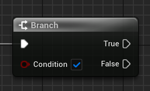
This node takes a ● Boolean as input and creates branching paths, one for if the condition isTrueand another if it isFalse.
More examples:
Flow Control : Loop
Loops allow you to iterate on a collection or repeat a block of code multiple times.-
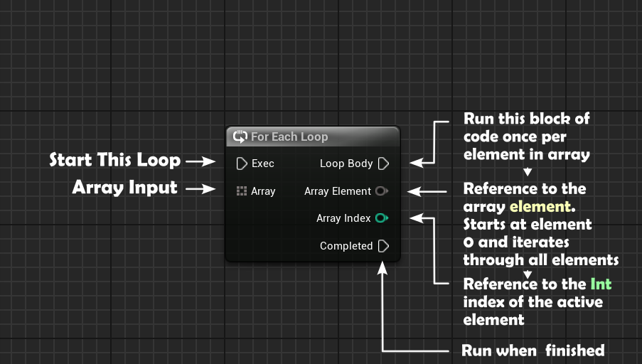
To iterate on an array, or loop through each item in a collection one-at-a-time, use a
Foreach Loop.
First, create a newStringvariable, and make it an Array. An array is a collection of similar data types, in our example it will be a collection of strings representing peoples names. -
In the Unlocked path of the button trigger sequence, add a
Foreachnode at the end. This node takes an Array as an input and executes the Loop Body path once per element in the array. Each time it runs that Loop Body path, the Array Element and Array Index value change to the next element/index in the array.
- The first time it runs, Array Element refers to array element 0, and Array Index is0.
-
Plug the
String Arrayinto theForeach Loop Array Input. -
From the
Loop Bodypin, add aPrint Stringfunction. This will be called once for each element in the array.
Plug theForeach Loop's Array Elementoutput into thePrint Stringinput to cause it to print out each element, one each time the Loop Body runs. -
Add a
Print Stringfunction to theCompletedpath on theForeachnode. This will alert us that the loop has finished printing out all the elements. - Once names are added to the array, and the button is triggered by the player, the names print out to the console.
-
To get an individual element from an array, use a
Getnode and provide anintfor the index of the element.

Note TheRandom Integernode returns a value up to the Max Value - 1
Mouse-over the nodes to see the details of how they operate.
Random
Random nodes can be used to add variation to behavior in your scripts.
Here is a Random Bool node plugged into a Branch node's Condition input.
This will trigger a 50% chance of getting True and 50% chance of False.

In this Custom Event, Take Damage, the amount of damage that a player takes is randomized to be
between 90% - 100% of the damage value passed into the event. Uses a Random Float In Range node to control the range or
random numbers it can return.

This Custom Event, Get Random Student, gets a random element from the String Array called "Names".
Uses Random Integer node with the max value set to the Length of the array.

Components
To reference a component in the Event Graph, drag the component from the Components panel onto the graph. With the component reference added to the Event Graph, it's properties can now be modified.-
On our Button example, add a Scene component. This is an "Empty" component that will serve as the parent and pivot point for
rotating another component around the button. It's position should be
0, 0, 0, the center of the button. -
Next, add a Cube component and drag it onto the Scene component to make the Cube a Child of the Scene component.
Resize the cube to flatten it and move it to the edge of the button so it protrudes out one side. -
With the Scene component (named "RotationPivot" in the example) selected, rotate it on the Z-Axis to see how it will rotate in our script. It's a
good idea to test how things will move this way before writing the script so that you know which axis to move/rotate on, and by how much.
Reset the rotation back to0, 0, 0after testing. - In the Event Graph, at the end of the unlocked button press sequence, drag the Scene component (named "RotationPivot" in the example) onto the graph.
-
From the Scene component, drag a line and add the
Add Local Rotationnode. Enter a value of0, 0, 10into theDelta Rotationproperty to cause the component to increase it's rotation on the Z-Axis by 10° each time the button is pressed.
Reference Other Actors
To allow one Actor to talk to another, a reference must be created. This can be something cached at the start of the game, a reference created inside the details of the level, or something found dynamically as it's needed.We will create a new Blueprint, a door, which will have a function that opens and closes it.
Then, we will give the button a reference to the door so that it can tell it to open/close when the player triggers it.
- First, create the new Door Blueprint with Actor as the parent class.
-
Create a Cube component for the Door. Scale the door to approximately the size you'll need. We can adjust this later.
Apply a material to the Cube.
Position it so that the bottom of the cube is on the ground, where the grid lie in the
viewport.
-
Open the Door's Event Graph window and remove the default events.
Right-Clickthe graph and findCustom Eventto add a new Custom Event which the Button will call.
Name it "ToggleDoor". - Create a ● Boolean variable to track the state of the door. Name it "IsOpen".
-
Add a
Branchnode to theToggleDoorevent. This will create a path for opening the door when it's closed, and closing it when it's open.
Use the value ofIsOpenas the condition for theBranch. -
To switch the state of
IsOpen, drag theIsOpenvariable on the graph and select Set. Set the value of the variable to the opposite of it's current value by getting it's current value and using theNotnode to invert it.
IfIsOpenisFalse, it will set the variable to (Not False), orTrue.
Note You can create Comments around selected nodes by pressing the "C" key. Your future self will thank you! -
From the
Truepath of theBranchnode, create aTimelinenode. This will help animate the doors movement over time. ATimelinenode provides a simple method of changing one value to another other some amount of time. So we will use this change in value to control the Door's Z-Axis value.
Double-ClicktheTimelinenode to enter the Timeline Editor -
At the top of the Timeline Editor select button
> Add Float Track. This will add a track for changing a
Floatvalue over time.
Name the track "DoorMove".
In the Length field next to the button set the Length of the track to 1 second. -
Because this value should move the door from CLOSED (up) to OPEN (down), the first value on the track should be the doors Z-Axis position
when it is closed. Look at the Viewport to verify this position.
Right-Clickthe track to add a node, which needs a Time and Value. This is the starting point, so set the time to0and the value to the doors start position on the Z-Axis,40.
Find the Z-Axis position the door should move to when opened, and add a node for that value atTime: 1.
With the start and end nodes set, press "F" to see both nodes laid out on the track. It should form a line sloping down, as the Z-Axis position value is moving from a high number to a low number. -
Once the track is set to move from the Closed Value to the Open Value over 1 second, use the
Updatepath to make a change every time the value of the ●Door Move Floatchanges. It will change many times over the 1 second, moving just a bit each time to create the animation.
Each time the value does change, the ●DoorMovevalue will be updated. - The component that we want to move is the Cube, or our Door, so drag a reference to the component onto the Event Graph. The change we want to make is to it's Relative Location, it's offset from its parent component. Use the Set Relative Location.
-
To set the value of the offset each Update, split the
New Locationinput byRight-Clickingon the pin and splitting it. You can now plug the ●DoorMoveoutput into theNew Location - Zinput.
The Door will now open when the event is called! Let's make the Button call it. - On the Button Blueprint, add a new variable. This will be a reference to the Door actor that this button should target, call it "DoorTarget". Change the variable type to Door, so that it can be set to a Door actor. Make it Public so that the reference can be set in the level's detail panel.
-
To make the Button tell it's
DoorTargetreference to open the door, drag theDoorTargetonto the graph and from the reference, find theToggleDoorCustom Event that you created on the Door Blueprint.
Make sure you execute this action by dragging in the white Exec line. - Add the Door to the level by dragging the Blueprint in. Position and scale as needed.
-
On the Button, find the
DoorTargetfield in the Details panel and set the value to the Door that is in the level.
The button should now trigger the door!
Get User Input & Spawn Actor
Use the Input settings inEdit > Project Settings > Input to map a new Input Action to detect a player
pressing the Left Mouse Button.Use the
Spawn Actor By Class node to create a new Actor from a Blueprint class.
-
Open the Input options in the Project Settings window by going to
Edit > Project Settings > Input.
Add a new Action Mapping called "Fire" which gets triggered by the player pressing theLeft-Mouse Button. -
Open the BP_First_Person Blueprint and add the new
Fireinput to the Event Graph.
AddPrint Stringfunctions to make sure the action is firing properly. -
We need a Blueprint for an object to spawn and throw when the user clicks the mouse. Create a new Blueprint and call it "Torch".
Create a tall cube with a smaller cube and Point Light on top. - Ensure that the main Cube component is the parent to the rest of the components. When we add physics to this torch, the parent component will have the physics enabled and the child components will remain attached.
-
Next, we need to set the physics and collision properties for the cubes. We want the torch to fall to the ground and bounce off of level geometry,
but don't want it to be kicked around by the player.
On the Cube component, enable Simulate Physics> inside the Physics category.
With the parent Cube and child Cube(Cube1) selected, disableCan Character Step Onand change theCollision Presetto Custom.
- In the Custom Collision Preset dropdown menu:
- ChangeCollision Enabledto Physics Only
- Object Type to PhysicsBody
- Then set Pawn and Physics Body to Overlap to prevent the Torch from colliding with the player (Pawn). - Drag a Torch into the level to verify the physics behave properly.
- To determine where to spawn the Torch, add a Scene component to the BP_First_Person Blueprint and position it in front of the player. A Scene component is a component with just a Transform, perfect for storing our spawn point.
-
In the BP_First_Person Blueprint, go to the Pressed pin on the Fire event and add a
Spawn Actor From Classfunction.
This Function creates an Actor by providing it the Blueprint class you want to create it from. Select "Torch" from the list of Blueprint classes.
-
The function requires a
Transforminput as well, data about the Position, Rotation, and Scale of the Actor you wish to create.
Split this struct and use theWorld Locationof the Fire Point Scene component as the Location input. -
Now that the Torch has been spawned, we can use the Return Value of the
Spawn Actorfunction to get a reference to the new Torch Actor, and add a Force to it. From the Return Value pin, add theAdd Forcefunction with the name of theSimulate Physicscomponent. In our case,Add Force (Cube) -
The Force we wish to add is a Vector in the direction that the Camera component is facing, multiplied by a large number to make it go far.
Get the Forward Vector of the Camera component, and use a Multiply node to extend that vector. I used roughly100,000for the X, Y, and Z, values.
Assignment 3 - Add Interactive Blueprints
The objective for the third Assignment is to update your Maze project with Blueprints.
You should create and use Blueprints that add interactivity to your Maze. Consider:
- Locked Doors
- Moving Platforms
- Elevators
- Shifting Walls
- Dropping Floors
- Health Potions
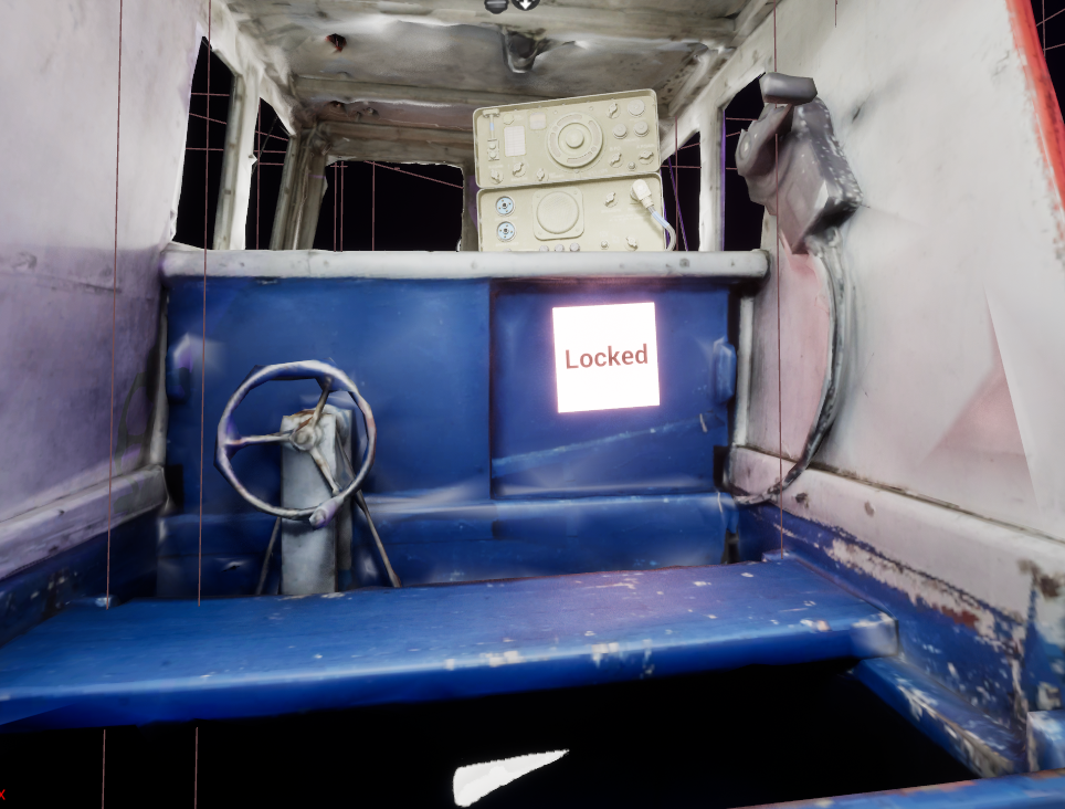
Example 1: Unlockable Lift

- Player must hit the switch to unlock the lift before it will activate.
- Switch can target a Platform.
- Platform detects player collision and moves up if it's unlocked.
Exercise 4 - Create A Landscape
Creating levels for your game often requires more than stacking Cubes throughout your level.
If you want to generate rolling hills, a daunting mountain pass, a calm lakefront camp site, or any other outdoor space, Unreal's Landscapes are the tool to use.
Lecture Recording Landscape Lecture on Zoom-
Before getting started with the Landscape, use the Fab explorer to find a material for the ground.
-
To create a new Landscape, open the Selection Mode dropdown at the top of the level Viewport and select
Landscape. - This panel will display the Manage tab of the Landscape options, allowing you to create a new Landscape. To set a default material for the landscape, select your material from the drop down menu. Then, click .
- Once the Landscape has been created, use the tools in the Sculpt tab to manipulate the terrain.
- In a future lesson we will look at how to create Landscape Materials so we can paint the landscape with different textures.
Exercise 4 - Adding Foliage
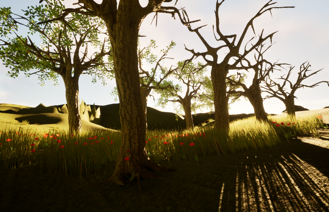
The Foliage painting tools in Unreal let level designers easily add foliage, trees, rocks, and other decorative actors, to their Landscape.
- Before getting started with the Landscape, use the Fab explorer to download foliage assets. You can use grass, flowers, plants, trees, rocks, and more.
- To paint foliage onto a Landscape, open the Foliage window from the Selection Mode dropdown menu.
- Select the Paint tool, and then add foliage assets to the list at the bottom of the menu. You can drag assets into the list, or search for them using the button.
-
To modify the properties of how a foliage asset should be painted, select one from the list and scroll down to see it's properties.
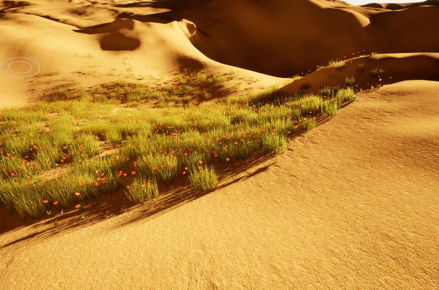
You can change the density of the asset, the randomized range of the scale for the asset, the angle of ground it should be allowed to attach to, and more! -
Enable the foliage you wish to paint by checking the ☑️ Check Box on the item.
You can then begin painting the selected items onto the Landscape.
Exercise 4 - Creating A Landscape Material
Landscape materials make use of Landscape Layers which can be blended together, allowing level designers a great deal of artistic
control over the look of their Landscape.
Documentation Landscape Materials
-
To create a Landscape Material, first download and extract the textures found in these two texture packs from AmbientCG (You can use other textures, be sure you have an Albedo texture and Normal texture for each):
- Create a new Material and name it "M_Landscape".
- Open the Material Editor Window and add a Landscape Coords node to your material graph.
- Add the Albedo and Normal textures from the "Ground" material to your graph. When dragged from the Content Browser, this will create a Texture Sample node for each texture.
-
Connect the output of the Landscape Coords node to the Texture Sample node's UV inputs.
I plug the Texture Sample RGB outputs into the result node to show that it renders the material, but this step is optional. - Add the Albedo and Normal textures from the "Rock" material to your graph. Position the Texture Sample nodes so that the Albedo textures are grouped near the top, and the Normal nodes the bottom.
-
Add a Landscape Layer Blend node between the Albedo Texture Sample nodes and the Result Node. With the
Landscape Layer Blend node selected, look at the Details panel.
Add a new Layer and set the name to "Dirt". This will create a "Dirt" layer for the material that will apply the various texture inputs labeled "Dirt" when painted onto the Landscape. - Create another Layer and name it "Rock".
-
The Landscape Layer Blend node will now display two inputs, one for each layer. Plug the
RGBoutput from the Albedo Texture Sample nodes into their respective input on the Landscape Blend Layer node.
Connect the output of the Landscape Layer Blend node to the Color input on the Result Node. -
Duplicate the Landscape Layer Blend node for use with the Normal textures. If you create a new Landscape Layer Blend instead of duplicating,
be sure to name the two layers exactly the same as the layer names on the other Landscape Layer Blend.
Plug in the inputs and output for the Normal textures. - Plug the Landscape Coords into the remaining Texture Sample node UV inputs.
-
Save the Material and select the Terrain in the Outliner panel. In the Details panel, change the material
for the Landscape to the new
M_Landscapematerial. The Landscape will turn black until we update the Landscape with Landscape Layer Info. - Open the Landscape mode from the Selection Mode dropdown, and select the Paint window. In the Layers list, the two layers for the material should appear. Each layer needs a corresponding Layer Info asset to allow it to be painted onto the Landscape. Click the "+" next to each layer to create this asset.
- You can now select the layers to choose which texture to paint with, and adjust the brush settings as needed. Draw onto the Landscape to see the materials blend together.
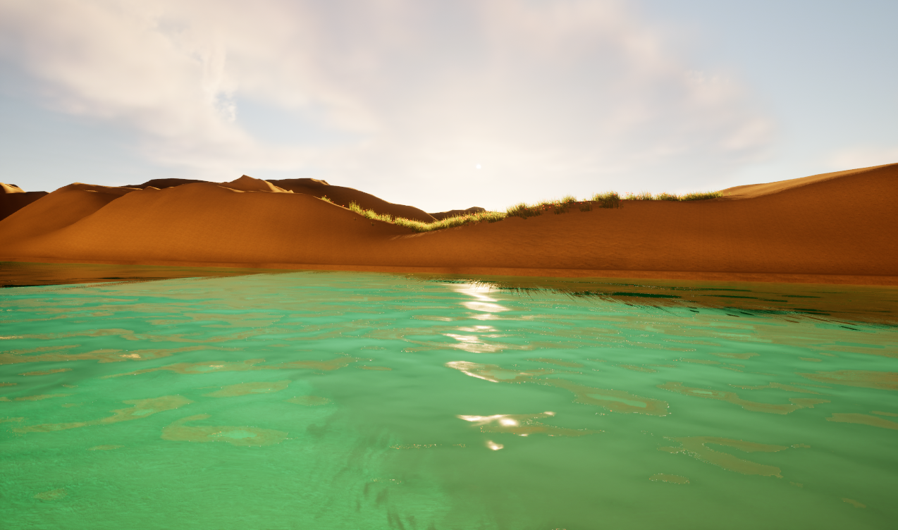
Exercise 4 - Adding Water
To add water to your project, you can add the Water plugin from the Plugins menu.
-
To add the Water plugin to your project go to
Edit > Pluginsand search for "Water".
Enable the ☑️ Check Box next to the Water Plugin and select to on the popup.
To enable the plugin you must restart the editor, so select at the bottom of the menu. - In the Quick Add menu, search for "Water". There are several water actors available. Select the Water Body River.
-
This actor creates a water path along a spline. Select a node to change it's position.
Right-Clickon the path to add a new point, and select the point to control it's position.
Select the point's handles to adjust the curve.
Assignment 4 - Landscape
The goal for Assignment Set 4 is to create a level that features a landscape the player can explore.
Consider adding vegetation, water, and other interesting elements to help create a believable world.
Exercise 5 - Create A Widget
A Widget allows you to create UI type game elements like a HUD, Menu, Labels, Damage Indicator, Map, and more. You can display text, images, and interactive elements like buttons and sliders. Widgets are designed in the Unreal Motion Graphics UI Designer.
-
This example is built on top of the earlier Inheritance example. It uses a Sphere Trace By Channel function to
detect collisions in front of the player during the BP_FirstPersonCharacter
Tickevent. This will be updated later to display the BP_Item's name Widget. -
To begin, create a Widget Blueprint. Choose "User Widget" as the Parent class. Name the new Blueprint "W_ItemName".
Double-Clickthe Blueprint to open the Unreal Motion Graphics editor. -
At the top-right of the UMG Editor, there are two options: Designer and Graph.
The Designer window is where the various UI widgets can be arranged on the Widget Blueprint.
The Graph allows for scripting the Blueprint. -
In the Designer window, add a Button to the Widget (I added a Canvas, which can be skipped for this example. We'll use this again later for our Player HUD).
Add a Text Widget as a child of the Button.
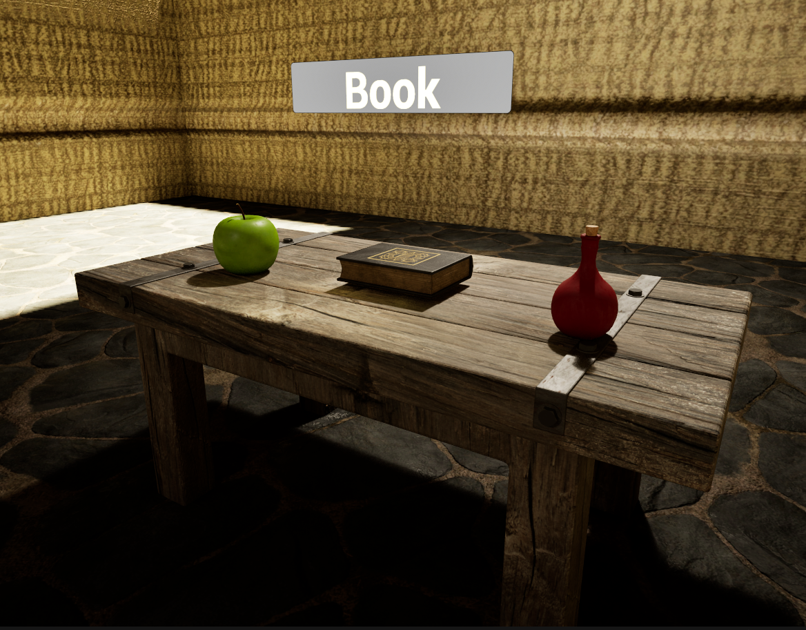
Adjust the colors as needed. The size can be adjusted later when we see how it looks on the BP_Item. - Next, we need to add a Widget component to display an instance of the Widget Blueprint we just created. In the example, this is being added to the base BP_Item. Child classes, Apple, Book, and Potion will inherit this Widget.
-
The Widget component needs to be told which Widget Class it should use, use the Widget Class dropdown to find your Widget Class.
You should now see your Widget in the Viewport. Use the Draw Size property to adjust the size. -
This label should be hidden at the start, and then shown when the player looks at the item. Find the Visibility property and toggle it
off. -
Next, we need to add a way for the text label on the Widget to be changed to show the name of the BP_Item it's attached to.
In the W_ItemName Blueprint, open the Graph window. You can remove the default events and add an new Custom Event called "SetNameText". This event should change the text value of the Text widget to say something besides "Item Name". -
To allow the Graph to modify the value of the Text Widget, the Text Widget must be a Variable. To do this, open the
Designer window, select the Text Widget in the Hierarchy, and check
Is Variable. You should also rename the widget to something more easily understood. Compile the Blueprint and switch back to the Graph window. The Text widget should appear as a Variable. - Add the NameText variable to the graph, and from the node it creates, add the Set Text function. This node requires a string to set the text to, so now we need a way to pass a string into the SetNameText function.
-
Select the SetNameText node, and add an Input. Call it "Name", and make it a
String. Now, whenever this function is called, it can be passed a string. Connect the SetNameText "Name" output to the Set Text string input.
This is an important concept for Widgets, creating functionality that allows other classes to call functions on them and letting them handle updating the required components accordingly. -
Now that the Widget has a method for setting it's text, use the Begin Play event on the BP_Item Blueprint
to call it.
The Widget Component attached to the BP_Item is not a W_ItemName, so you cannot access the SetNameText function from the Widget component reference. From the Widget component you will need to use theGet Widgetfunction and then cast the result to the W_ItemName Widget. This will allow you to call the function SetNameText.
Use the Self node to get a reference to the Actor that was made from this Blueprint, and then use its Display Name as the input for theSetNameTextfunction.
To test this, set the Widget Visibility toTrue. -
When the game begins, the item's Widget components will have their name set and the visibility set to
True. -
Next, we need the name to display when the player looks at the Item instead of when the game begins. On the Item, create a Custom Event
called "LookAt". It should use the
Set Visibilityfunction to make it visible, and then use aRetriggerable Delayto set the visibility back to false after a short delay. This will cause the delay to reset every time theLookAtfunction is called, which will be every frame that the player is looking at it. -
Finally, change the BP_FirstPersonCharacter so that instead of printing out the name of the actor it hits with the
SphereTrace, it Casts the Hit Actor to a BP_Item and calls theLookAtfunction on it.
Exercise 5 - Player HUD (Heads Up Display)
To create a Player HUD, often used to display Health, Ammo, Maps, Menus, etc., we can utilize a Player HUD Blueprint.
The Player HUD maintains references and functions to control the Widgets which show the various elements. This creates a central
point of control for handling all of the various UI elements for a player.
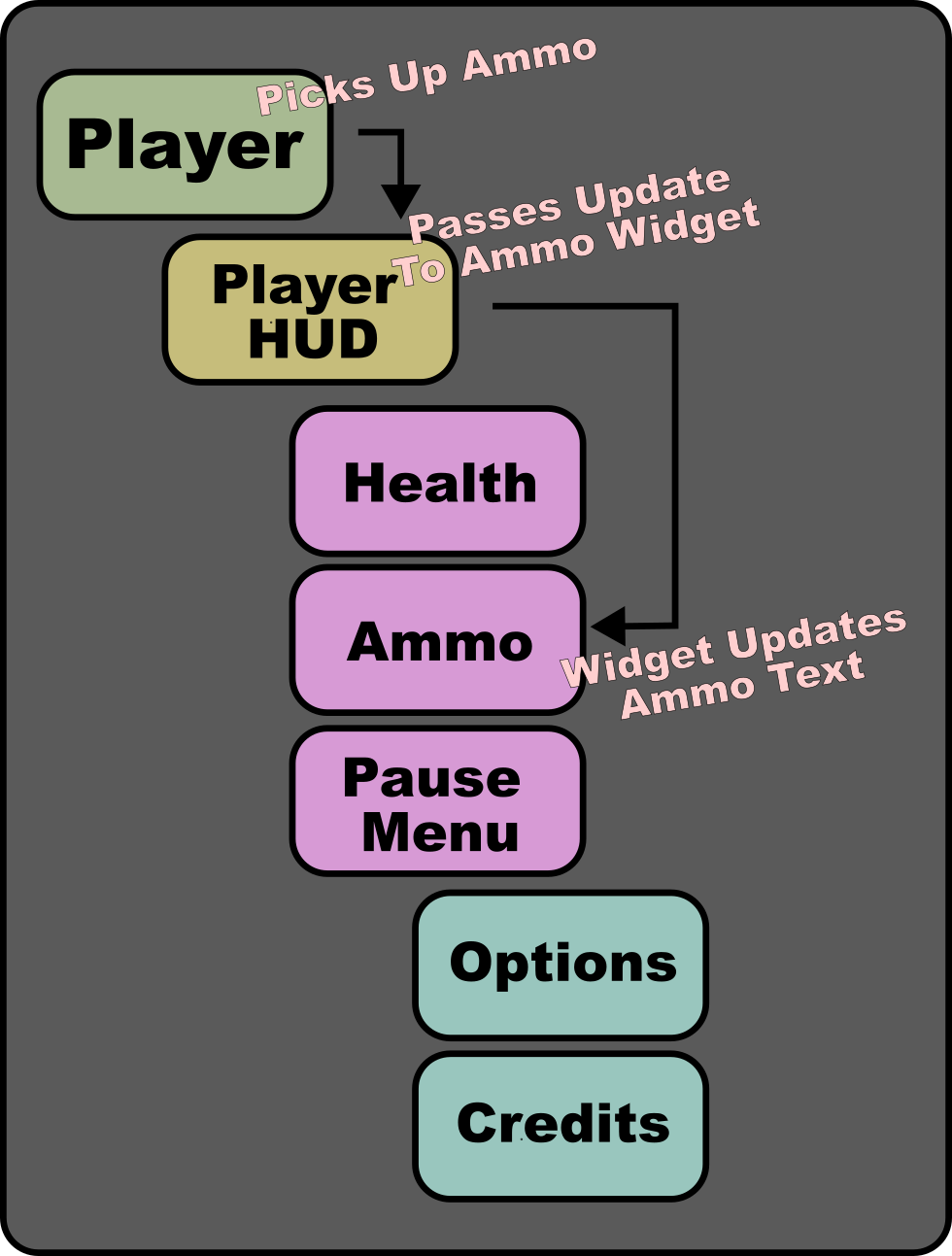
In the Player HUD example we will create a W_Health Widget which displays the players health in the corner of the screen. A BP_PlayerHUD
Blueprint will manage this Widget with a function Update Health, which the BP_FirstPersonCharacter will call when their health changes.
- First, create a Blueprint which uses the HUD parent class. Call it "BP_PlayerHUD". This Blueprint will maintain references to the various Widgets the player needs, and contain the functions used to interact with them. Those will be added later.
-
Create the health Widget Blueprint, inheriting the User Widget parent class. Name this Blueprint "W_Health".
This Widget will contain references to the text component that appears on the screen, and contain a function that can be used to update the text with the current health value, which will be called by the Player HUD.
Open the W_Health Widget to launch the Unreal Motion Graphics editor. -
From the Panel category, add a Canvas component to the Widget by dragging onto the graph or the Hierarchy. This component will allow
your Widget to be anchored and scaled to fit a users screen properly.
From the Common category, drop an Image component as a child of the Canvas. This will serve as a background on which the health text is drawn. Use the Anchors dropdown to select the anchor points that stretch the Image along the bottom of the Canvas. HoldShift + Ctrlwhile clicking to update the Image alignment and position to match the new Anchors as well. This will cause the image to stretch to fill in the bottom of the Canvas.
Next, from the Common category, add a Text component to the Canvas. Anchor it to the Bottom-Left corner, and change theTextvalue to "Health". Change the name of the Text component to "HealthText", so that it's easy to find later when the Widget script needs to change the text. ✅ CheckIs Variableto allow the text to be changed via a script. -
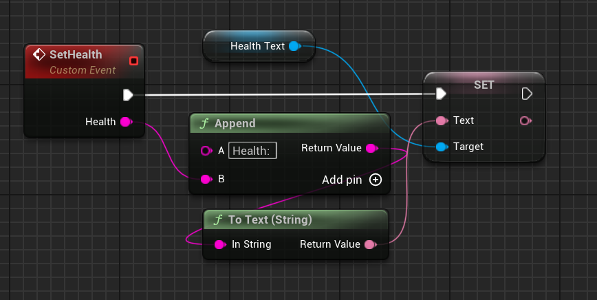
Switch to the Graph editor and create a Custom Event called "SetHealth". This will be called by the Player HUD, when the player's health changes, to change the text.
Add a ●String variable to the Input of this event, so that the updated player health value can be passed in. Drag the HealthText component onto the graph from the Variables list to get a reference to the health text component. From this node, use theSet Textfunction to change the text.
TheHealthstring passed into this event will be the value of the players health, ex: "100". To get the UI to display "Health: 100", use aString Appendfunction to combine strings together. The first string should be "Health: " and then append theHealthvariable to that.
-
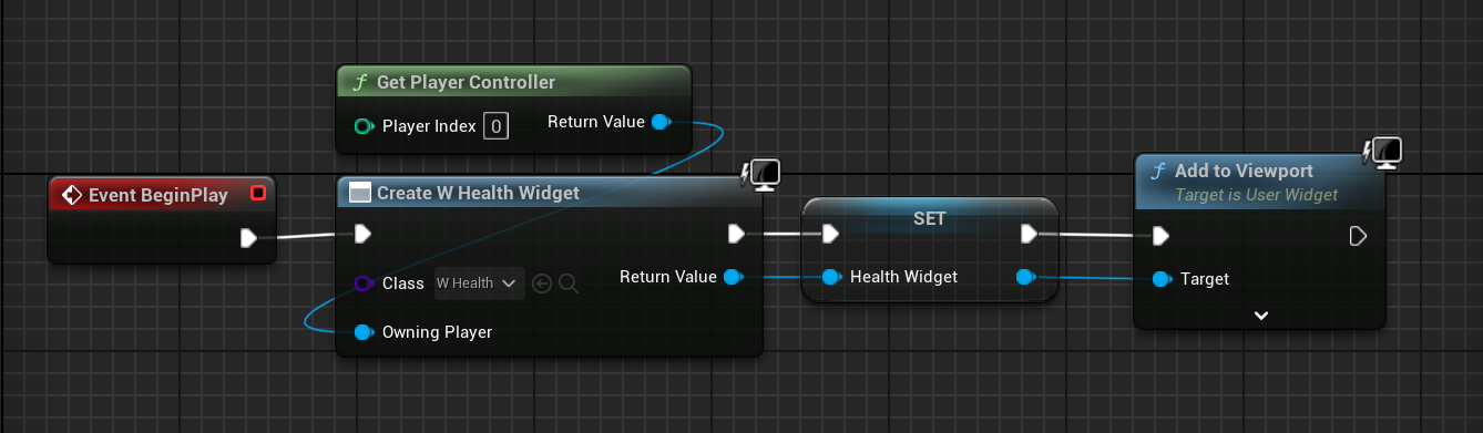
Now the Player HUD needs to create one of these W_Health Widgets when it begins. Open the BP_PlayerHUD Blueprint and give the
class a "HealthWidget" variable with the
W_Healthtype.
From theBegin Playevent, add theCreate Widgetfunction. Set the Class toW_Healthto create an instance of theW_HealthBlueprint. Set the Owning Player to theGet Player Controllernode for Player Index 0. Next,Setthe value ofHealthWidgetto theReturnValueof theCreateWidgetnode to save the reference to our new Widget instance. Finally, use theAdd To Viewportfunction to display this Widget.
-
To tell this level that it should assign our BP_PlayerHUD as the HUD for the player in this level, open the World Settings window. And
set the Game Mode to
BP_FirstPersonGameMode. This is the Game Mode Blueprint that comes with the First Person Template we started from.
Open the BP_FirstPersonGameMode and change theHUD Classto the BP_PlayerHUD we created earlier.
When you run the game, the HUD should now appear. -
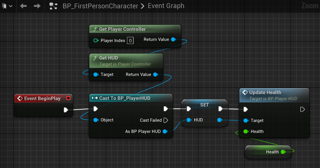
To connect the BP_FirstPersonCharacter Blueprint to the BP_PlayerHUD, add a BP_PlayerHUD variable called "HUD" to the BP_FirstPersonCharacter Blueprint. Use the
Get HUDfunction to get the HUD assigned to this actor, and then Cast the result to our BP_PlayerHUD. Set theHUDvariable to the result of this cast.
Add a ●Float variable called "Health" to the BP_FirstPersonCharacter Blueprint to track the players health. -
Next, to allow the Player HUD to handle changes to the player health, open the BP_PlayerHUDBlueprint and add a new Custom Event called "UpdateHealth". Add a ●Float input
called "Health" to this function so that the player can pass in their health when they call this event.
Use the reference to the Health Widget to call theSetHealthfunction and pass in theHealthvalue.
Now that the BP_PlayerHUD Blueprint has aUpdateHealthfunction, go back to the BP_FirstPersonCharacter Blueprint and have it callUpdateHealthon the HUD when it starts.
-
The HUD should now accurately display the players health.
Add a way to change the players health, then callUpdateHealthon the BP_PlayerHUD to ensure the HUD always displays the correct health value.
Assignment 5 - Add User Interface
The objective for the third Assignment is to update your Maze project with a UI.
You should create and use a Player HUD and at least two Widgets. Consider:
- Player HUD
- Health
- Inventory
- Map
- Other Widget
- Computer/Television Screen
- NPC Dialog
- Enemy Health Bar
- Waypoint Markers
- Objective Labels
- Health
- Inventory
- Map
- Computer/Television Screen
- NPC Dialog
- Enemy Health Bar
- Waypoint Markers
- Objective Labels
Exercise 6 - Animation
In this Assignment Set we will learn how to add characters and animations from Mixamo to explore animating models in Unreal.
NoteWe will be using the Third Person Template in this lesson and changing the Third Person Blueprint's Mesh and Animations. It might be most efficient to
start a new Unreal project with the Third Person Template for this example.
Importing Animations
-
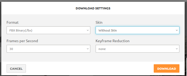
We will be using Mixamo to download a character mesh, textures, and animations.
Select a model from the Characters list and download the model as a
FBX Binaryfile. Save this model into your project's Content folder.
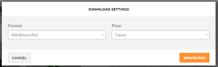
-
Next, download an Idle, Walking, and Jump, animation.
UseFBX Binaryformat andWithout Skin.
Be sure to ✅check In Place for walking animations, if available.
-
In the Unreal editor you will see a prompt for the import settings of the new assets.
For the Character model, leave the default settings and select Import.
For your animations, open the Skeleton selection drop-down and find the skeleton of the character you imported. -
In the Unreal editor you will see a prompt for the import settings of the new assets.
For the Character model, leave the default settings and select Import.
For your animations, open the Skeleton selection drop-down and find the skeleton of the character you imported.

-
An Animation Blueprint controls animation behaviors.
Create a new Animation Blueprint in your Content Drawer.

-
You will need to select a skeleton for your Animation Blueprint to target. Choose the skeleton associated with the character you imported.

-
In the Animation Blueprint editor, open the AnimGraph window.
Here you can find the Output Pose node on the graph. This node represents the animation which is being played on the skeleton. We will plug various nodes into the Output Pose node to control which animation it is playing.

-
Sequence Player nodes can be plugged into the Output Pose node. You can drag an animation from your content
drawer into the graph to add one.
We wil be using a State Machine to control which animations are influencing the output.

-
A State Machine allows for control over which animations are influencing the output.
Add a state machine to your graph. Then double-click the State Machine node.

-
Inside the state machine, right click to create new states. Create a Movement state and a Jump state.
Then, drag the Entry pin onto the edge of the Movement node, to have our state begin there.
Next, click and drag the edge of the Movement state and drop it on the Jump state. This will create a transition between the states.
Do the same from Jump to Movement.

-
Open the Jump state and add the Jump animation to the graph. Connect the Jump sequence to the Output node.
This will cause the jump animation to play when the Jump state is entered inside this state machine.

-
Now we need to enable the transition from the Movement state to the Jump state.
Open the transition going from Movement to Jump.
Enable the transition.

-
To control the transition between the Walk state and Jump state, we need to write a script in the Animation Blueprint's Event Graph
Open the Event Graph window and add aboolvariable called "On Ground". The state of this variable will control when we transition between our Movement state and Jump state.

-
We can reference the ThirdPlayerBlueprint using
TryGetPawnOwner. Then, to check the movement properties, useGetMovementComponent. From there, we can check the value ofIsFallingto see if the player is in the air.
If the player is in the air, they are not on the ground, so we can use thenotnode to invert the value of the bool and then set our "On Ground" variable to the output of that node.
Use theEventBlueprintUpdateAnimationevent to call thisSetfunction each frame.
Now we have a bool that is constantly updated to tell our State Machine if we are on the ground or not.

-
Next, we can use that On Ground bool to trigger a transition from our Movement state to our Jump state.
In the State Machine, open the transition from Movement to Jump. We need to plug a boolean value into "Can Enter Transition", so by taking the value of "OnGround" and then using thenotoperator to flip it, we can cause this transition when we are not on the ground.

-
For the Movement state, we want to be able to blend between our Idle and Walk animations.
In the Content Drawer, create a new Blend Space asset (Animation > Blend Space)
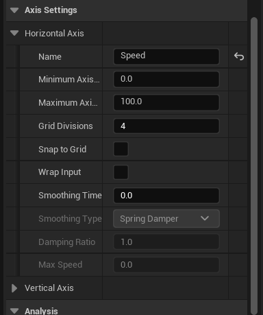
A Blend Space asset defines how much a set of Animations should influence a rig based on the value of a variable (1D) or multiple variables (2D). -
Define a Horizontal axis named "Speed". The value of "Speed" will determine how much influence our Idle or Walk animation has on the rig. Here's an example that includes a Run animation as well:
- AtSpeed == 0the animation should beIdle
- AtSpeed > 0 and Speed < 0.25the animation should beWalk
- AtSpeed >= 0.25the animation should be blending betweenWalkandRun. As theSpeedincreases, the animation should play lessWalkand moreRun
- AtSpeed >= 1the animation should beRun
-
Drag the Idleanimation from the Asset Browser panel onto the Timeline to add a blend sample. The Idle sample
should be set at the far left of the line, and can be adjusted later.
Add the Walk animation from the Asset Browser panel twice. We'll use it once for a regular walk, and then a sped up version for our run. On the Asset Details panel there will now be three Blend Samples,Idle, Walk, Walk. Set the speeds to:Idle: 0.0
Walk(1): 10.0
Walk(2): 100.0, Rate Scale: 2.0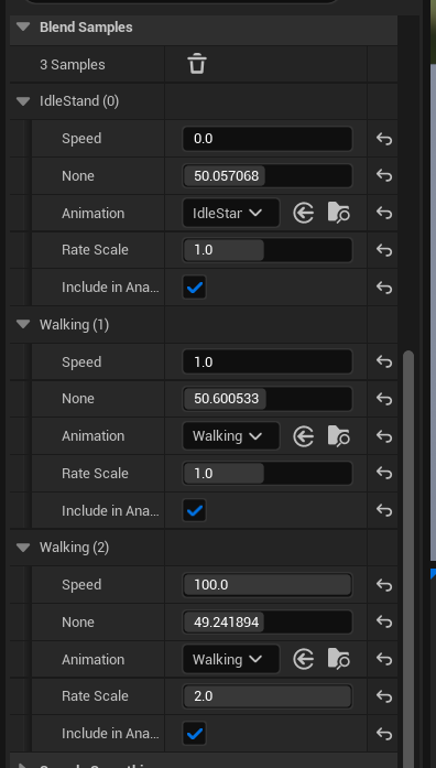
-
Hold
Ctrland scrub the mouse along the timeline to preview the blends at different Speed values.
-
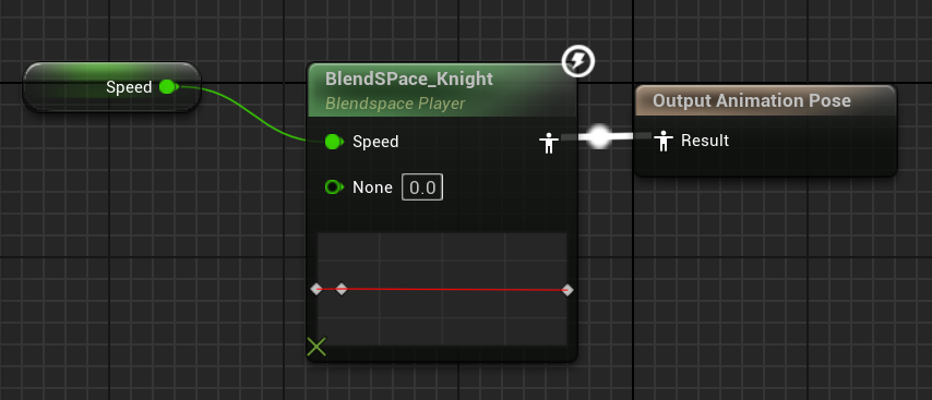
In the Animation Blueprint, add a ●Float variable called Speed. Then,
add the Blendspace to the graph. Plug the
Speedvariable into theSpeedinput on the Blendspace node. The Blendspace node will handle blending the animation based on the value of Speed, so the player just needs to update that value.
-
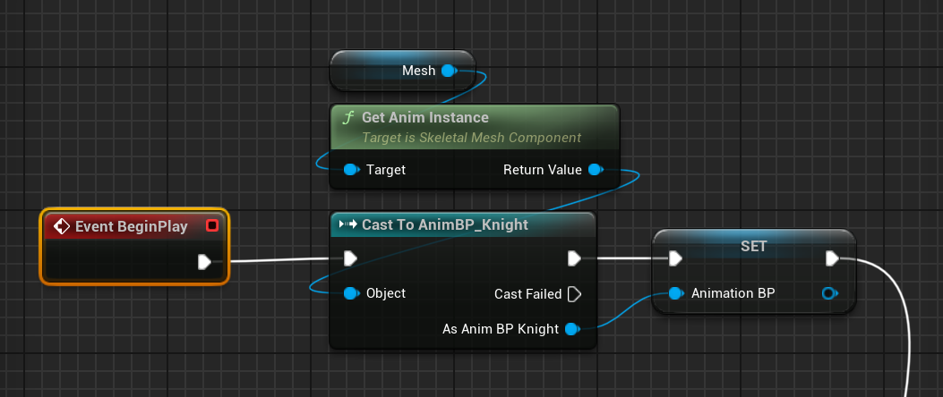
In the BP_ThirdPersonCharacter Blueprint, create an Animation Blueprint variable to store a reference to the knight's Animation Blueprint.
-
Finally, in the BP_ThirdPersonCharacter Blueprint's
Tickevent, update the Animation Blueprint with the players speed by getting a reference to the Character Movement component, getting it's Velocity, and then getting the Length of that vector, as the speed for the Animation Blueprint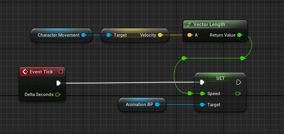
Animation Blueprints
State Machines
Assignment 6 - Add Animation
The objective for the third Assignment is to add your own character model and animation to a game.
Git for Unreal
Version Control in Unreal Engine
- With Git
- Install Git and GitLFS
- Download Git for your operating system.
- Install using the recommended settings.
- Download and install GitLFS.
- Setup Git
- Open Git Bash and set your user details by typing:
git config --global user.name "Your Name”git config --global user.email “Your Email”- Using GitHub Desktop
- You can also use GitHub Desktop to manage your repo.